Intro to Sound Circuits
Context
Digital oscillators
Analog oscillators
Our plan: a gentle intro to analog oscillators using integrated circuits (ICS)
- ICs encapsulate complex circuits so we don't have to worry about the details.
- If you already know all this stuff, you may want to meet my friend Jeff at Princeton.
Resources
Places to buy audio gear
- NYC Stores
- Radio Shack
- 269 Electronics (269 Canal Street, back of store)
- Online
Online books and tutorials
NYU's Interactive Telecommunications Program (ITP): physical computing tutorials
Nic Collins' "Hardware Hacking" book
- This is a slightly less professional-looking version of Handmade Electronic Music, with almost identical content (and free!). See in particular Chapters 18 and 20.
Building
Baggie contents
- 1 cheap audio amp with speaker attached
- This amp uses a 386 integrated circuit (IC), which you can buy at Radio Shack for like 2 bucks (datasheet here).
- 1 9V battery snap
- 1 integrated circuit, or IC (4093 Quad 2-input NAND Schmitt Trigger)
- Datasheet here. This is the heart of our oscillator. See "Hardware Hacking" p. 75.
- 1 1µF (read: one microfarad) capacitor
- A capacitor is basically a battery; it charges and discharges.
- 1 1KΩ (read: one kilohm) resistor
- 1 potentiometer, or pot.
- A pot is a variable resistor.
- 1 red LED
- various wires of different lengths and colors
In addition, we will give you:
- 1 breadboard
- 2 batteries
Breadboard fundamentals
- http://itp.nyu.edu/physcomp/Labs/Breadboard
- Hardware Hacking p. 65
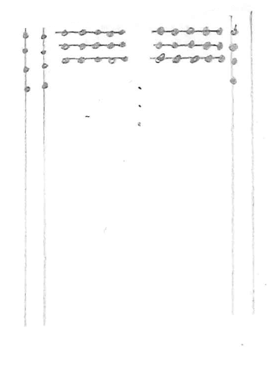
Layout of conductive metal strips under the breadboard performations. There are generally two long strips running down each side for power (+) and ground (-) and many rows of perpendicular strips down the middle.
Circuit 1: turning on an LED
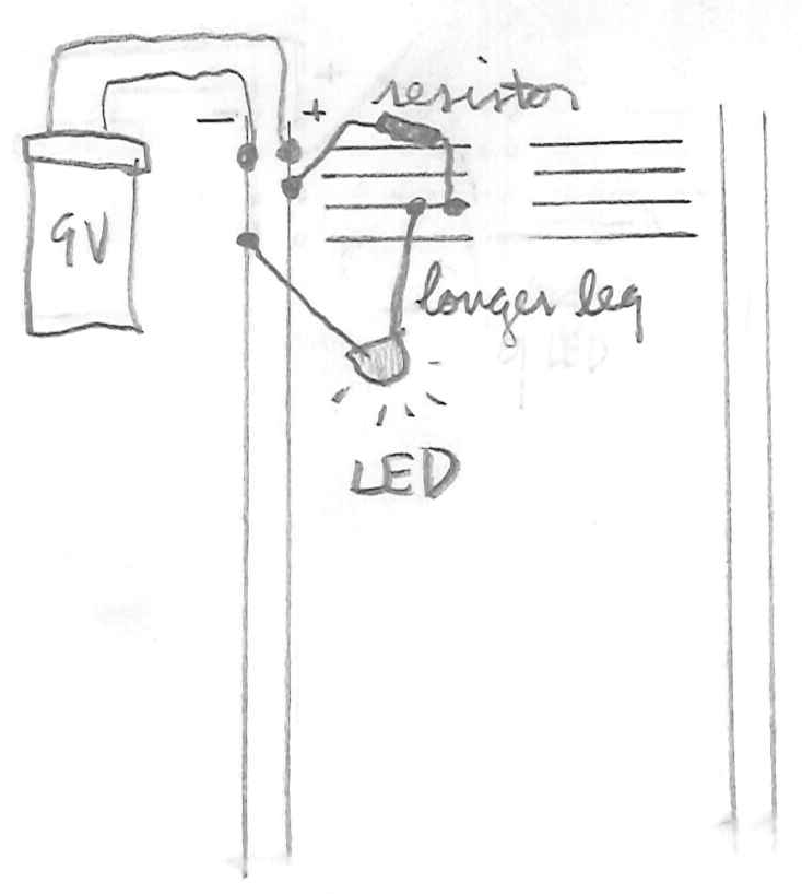
One way to hook up circuit 1 on a breadboard.
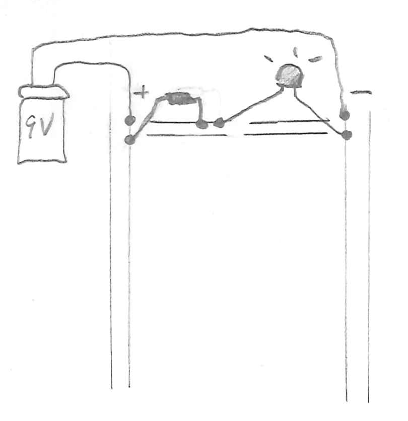
Another way.
An abstraction of the circuit, emphasizing its topology rather than its physical arrangement on a breadboard.
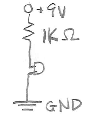
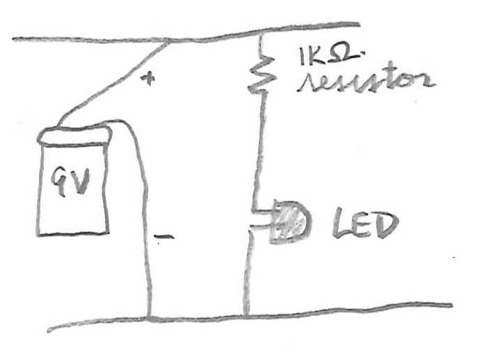
A circuit diagram that abstracts away the battery wires.
Circuit 2: swapping out a resistor for a pot to fade the LED
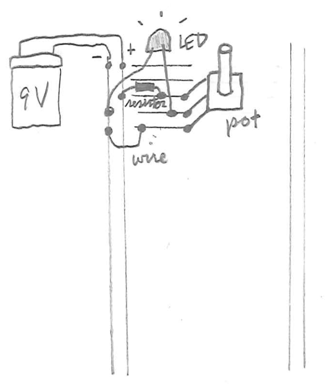
Fader hook-up. NOTE: the pot's resitance varies between 0 and 10K or 20K ohms. If it's turned down all the way, the circuit will short because there's no resistance, and the LED will give off a funny burning-plastic smell and stop working (as we discovered in class!).
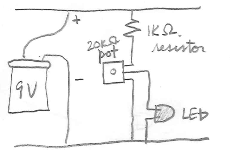
An abstraction, showing the connections to the pot.
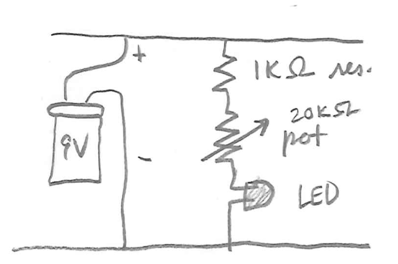
A deeper abstraction, representing the pot with its official symbol. The pot's connection to ground is implied.
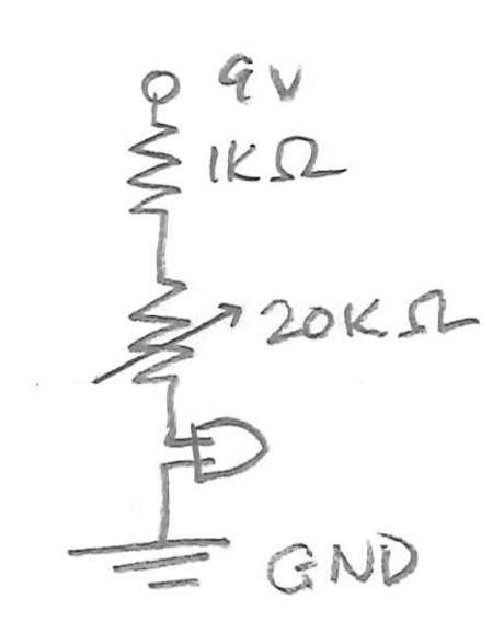
A circuit diagram.
Circuit 3: building an oscillator with the 4093 IC
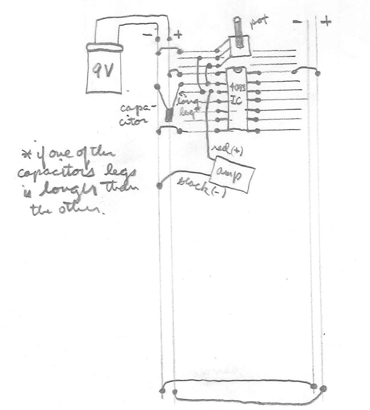
Oscillator hook-up. Orient the IC with reference to the its semicircular intent. Unmarked components are wires. Note the wires at the bottom of the board running power (+) and ground (-) to the long strips on the other side.
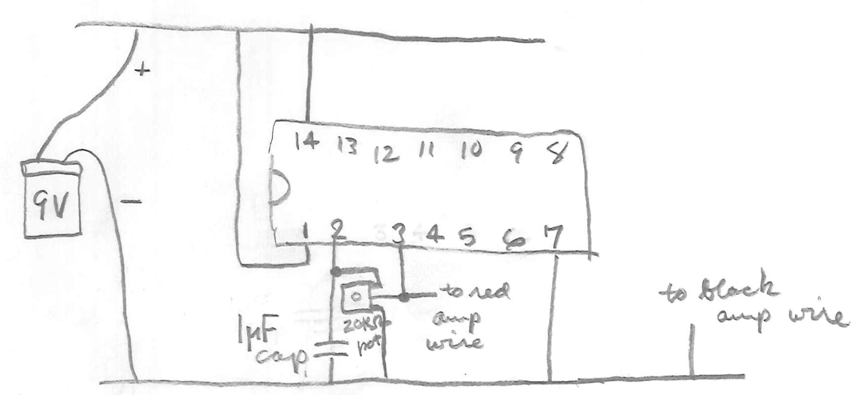
Abstraction 1, definitely not drawn to scale.
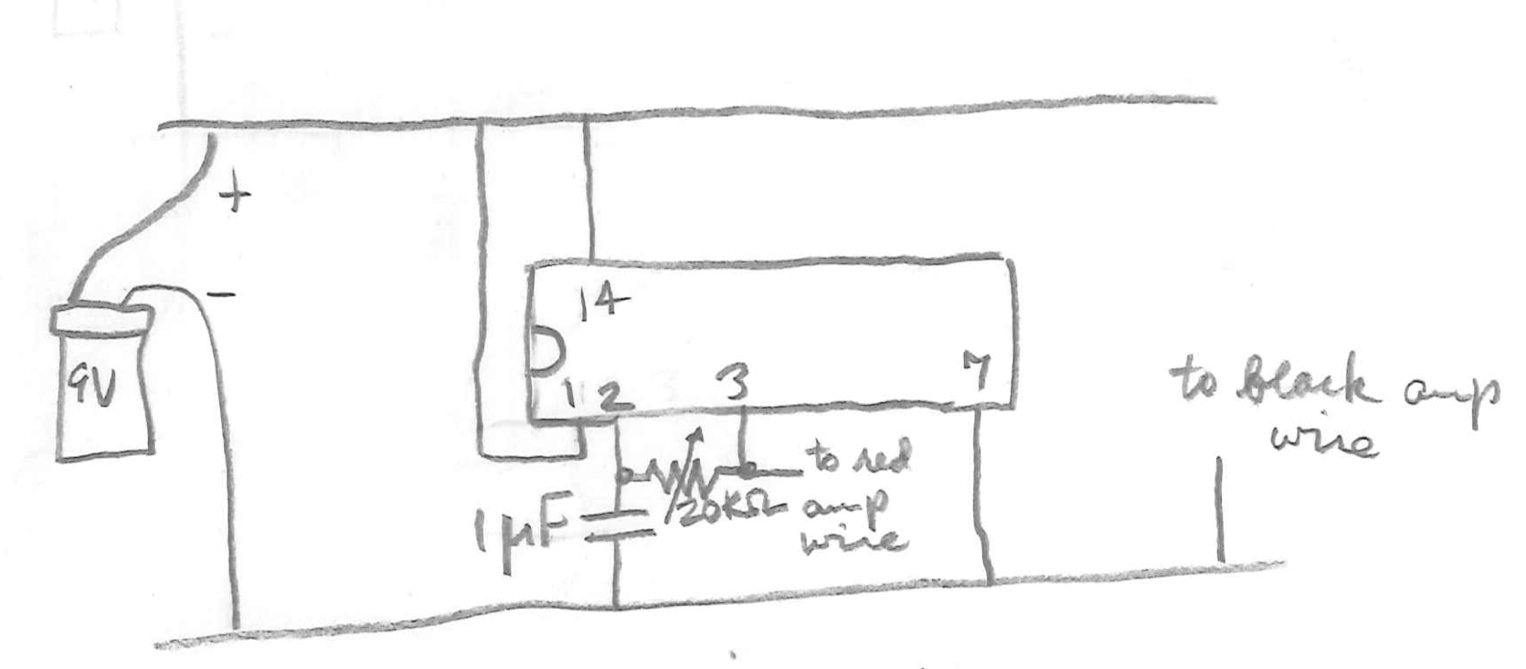
Abstraction 2, replacing the pot with its official symbol.
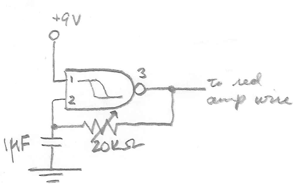
Circuit diagram, representing the logic inside the IC (a NAND Schmitt trigger) rather than the IC itself. See the datasheet and "Hardware Hacking" page 75 for more info. The IC ground and power are implied, as is the amp ground.
- To keep track of everything, you may find color-coded wiring helpful:
- 1 longish red: breadboard power
- 1 longish black: breadboard ground
- 1 shortish red: IC power (pin 14)
- 2 shortish black: IC ground (pin 7), pot ground
- 1 yellow: IC oscillator 1 input 1 power (pin 1)
- 1 green: from IC oscillator 1 input 2 (pin 2) to pot
- 1 blue: from pot to from IC oscillator 1 output (pin 3)
This document was generated on 2011-12-20 at 14:07.